Standard Electrical Symbols For House Plans will be the topic of our conversation on this particular occasion. There is, without a doubt, a great deal of information pertaining to Electrical installation plans in Draw available on the internet. As a result of the rapid development of social media, it is now much simpler for us to acquire new information.
There is a connection between the pieces of information pertaining to Designing Buildings - The Construction Wiki, standard electrical symbols for house plans, and Electrical Symbols Socket. Regarding the other items that need to be searched, one of those things is concerning Autocad Electrical Symbols Blocks Free Download, which will also have something to do with Basic Electrical Symbols.

20 Facts Standard Electrical Symbols For House Plans | Floor Plan Symbols and Abbreviations to Read Floor Plans
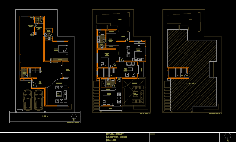
- The floor plan of a building, texts with e.g. the names of the rooms, circuit symbols, dimensions, circuit numbers (or other notes) etc. are inserted one above the other in a Draw document. - Source: Internet
- is a part of a field-effect transistor from which carriers flow into the inter-electrode channel. Ideal source includes an ideal voltage source and ideal current source. An ideal source is a theoretical concept of an electrical current or voltage supply (such as a battery) with no losses and a perfect voltage or current supply. Ideal sources are used for analytical purposes because they cannot occur in nature. - Source: Internet
- It is easy for you to create an electrical diagram when you know where to find thousands of electrical symbols. You can watch the video below and learn how to create an electrical circuit diagram. Alternatively, you can follow the instructions of words and pictures step by step. - Source: Internet
- The majority of industrial piping is designed to transfer liquids and gases used in manufacturing processes. The piping is used in all kinds of applications in commercial and residential buildings and generally is known as “plumbing” and it is designed to carry freshwater, liquid and solid wastes, and gas. All pipe fittings, fixtures, valves, and other components are represented by symbols in a plumbing drawing. - Source: Internet
- According to VOB C, DIN 18382 Para. 3.1.7, before the completed installation is put into operation, the contractor (electrical trade company) must carry out a test for operational capability and a test in accordance with DIN standards (usually DIN VDE 0100-610 for new installations). - Source: Internet
- In this step, a scaled drawing of the rooms is drafted on a graph or through the software. The scaled drawing should include the detailed features and positioning of cabinets, furniture, counters, stove, bed, table, chairs, etc. It is similar to an architectural drawing hence, it should be drawn using proper symbols. - Source: Internet
- Example one: There are three D-cells placed in a battery pack to power a circuit containing three light bulbs. The resistor symbol represents each light bulb. The connecting lines are used to connect the symbols. At the same time, don’t forget to put the switch in the circuit to control the current flow. The final sketch is shown in the following picture. - Source: Internet
- includes an ideal voltage source and ideal current source. An ideal source is a theoretical concept of an electrical current or voltage supply (such as a battery) with no losses and a perfect voltage or current supply. Ideal sources are used for analytical purposes because they cannot occur in nature. Resistor is a device that has resistance to the passage of an electric current. - Source: Internet
- Proper planning is a must for the electrical wiring layout. A decision about the wiring before plastering saves time. It can run through the interior or exterior of the walls, or beneath the floors. - Source: Internet
- Let’s start with architectural symbols, which are typically larger and will be drawn into floor plans first. Doors, windows, stairwells, walls, cabinets, and sinks are examples of these. Reading blueprints generally requires a strong understanding of line types. - Source: Internet
- The interior of a building is the starting point for the electrical installation. In a good plan, the switches for air-conditioners, ceiling fans, and lights are placed next to exits or entrances. Outlets are placed near the tables, cabinets, furniture, and table. The placement of switches for television, washing machine, computer, etc. should be planned accordingly. - Source: Internet
- Step 1: Launch EdrawMax on your cpmputer. An extensive collection of electrical diagram templates can be found in the Electrical Engineering category. Click the icon of Basic Electrical to open the library that includes all symbols for making electrical diagrams. - Source: Internet
- You can depict a complex electrical circuit with the standard and simplified electrical symbols. Therefore, anyone who knows of electrical and electronic circuits can read, understand, and build electrical diagrams quickly. The symbols image are below. - Source: Internet
- The basic electrical symbols are used to simplify the drafting and to help people understand the electrical drawing. Electrical symbols are standardized throughout the industry, so it is easy to achieve the ability to interpret the meaning of the symbols. With the standard electrical symbols in Edraw, you can create a circuit diagram that shows the actual layout of the components simply and quickly. The symbols image are below. - Source: Internet
- Example two: Three D-cells are placed in a battery pack to power a circuit containing three light bulbs. Firstly, quickly figure out which electrical symbol shall be used in the diagram. Then, think about the layout of these symbols. Last but not least, use a connector tool to connect all the electrical symbols. - Source: Internet
- The legend is often printed along with the title block at the bottom of the right side of the sheet. This is because it houses several architectural notations, and many of them are standardised symbols that would appear on every floorplan. There could be slight variations, but the basic outline would remain the same for all. - Source: Internet
- These symbols are like a different language that you need to learn. Professionals in the construction and design industry use this language to communicate effectively. Most floor plans also include legends that describe the colours, symbols and text the floor plan uses to leave no room for miscommunication. - Source: Internet
- As a client or a novice in the field of interior design, you may get lost in the sheer amount of architectural symbols, texts and numbers you see on an architectural plan. It could appear daunting to understand these symbols precisely. But it would help if you learned about them so that no miscommunication arises between you and the people you work for and with. - Source: Internet
- Welding symbols are used to represent all the details about welding, connections, joints for the machine, machine parts, or other building parts like windows, doors, railing, etc. Usually, these symbols are used by designers, such as a shop foreman, welding engineer, or supervisor, and welder. They mentioned all these symbols on engineering and fabrication drawings in order to create their weld, the welder will refer to this drawing. - Source: Internet
- Electrical symbols play a vital role in circuit diagrams. There are many standard symbols to represent specific components in a circuit diagram. EdrawMax will help you learn the usually used symbols for drawing circuits. Some electrical and electronic schematic symbols are used to signify electrical and electronic devices. When creating circuit diagrams, we primarily use these. - Source: Internet
 To get you started, here are some pointers to consider when searching for information regarding Floor Plan Icons:
- Do some research to find Electrical Plans-related information from reputable sources. This may include professional journalists, as well as online libraries and other websites.
- When looking for information regarding Electrical Symbols Socket, it is crucial to be aware of the various types of sources that can be found through electronic media. Some examples of these types of sites include Google and YouTube. There is also the possibility of obtaining information about Guidelines to basic electrical wiring in your home and similar locations from various social media sites, such as Facebook and Twitter. This is another another potential source.
To get you started, here are some pointers to consider when searching for information regarding Floor Plan Icons:
- Do some research to find Electrical Plans-related information from reputable sources. This may include professional journalists, as well as online libraries and other websites.
- When looking for information regarding Electrical Symbols Socket, it is crucial to be aware of the various types of sources that can be found through electronic media. Some examples of these types of sites include Google and YouTube. There is also the possibility of obtaining information about Guidelines to basic electrical wiring in your home and similar locations from various social media sites, such as Facebook and Twitter. This is another another potential source.Video | Standard Electrical Symbols For House Plans
Reading and doing research on the authenticity of each source are both essential if you want to discover the greatest information there is about Floor Plan Icons. Your understanding of Autocad Electrical Symbols will be improved by watching the many videos on Autocad Electrical Symbols that are included in this page. These films come from a variety of different sources. Finding knowledge on a wide range of subjects is made much simpler by making use of the internet as a resource.
## Here are some crucial points concerning Floor Plan Icons:- Standard Electrical Symbols For House Plans
- Electrical Symbols Pdf
- Autocad Electrical Symbols
- Floor Plan Icons
- Electrical Symbols Socket

You won’t have any trouble finding the information you’re looking for because there are so many websites and forums on the subject of Autocad Electrical Symbols Blocks Free Download.
When it comes to obtaining information on standard electrical symbols for house plans, the majority of individuals are more accustomed to using a different route. It enables a more in-depth look at the information regarding Electrical installation plans in Draw’s content and how it may be used, which is really helpful.

strategies to design information displays that are both aesthetically pleasing and functional that pertain to Basic Electrical Symbols and Their Meanings. They are useful in commercial and marketing settings, and they can also be put to use to convey information on Electrical Symbols Socket. As a result, we also supply some photos pertaining to Floor Plan Symbols and Abbreviations to Read Floor Plans.
In summary, this article offers a comprehensive analysis of Basic Electrical Symbols and Their Meanings. In addition, Basic Electrical Symbols and Guidelines to basic electrical wiring in your home and similar locations are mentioned here as a comparison of your knowledge regarding Dwg Electrical Symbols.